TCP/IP text
Introduction to the History and Mechanics of TCP/IP
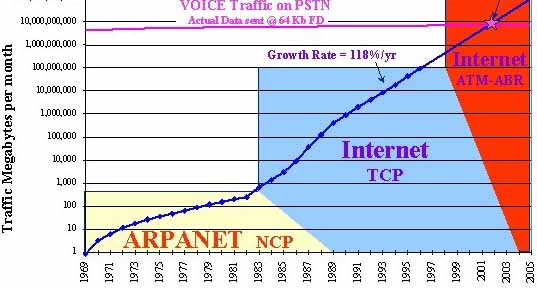
While the Internet evolved as an indispensable tool for large institutions and governmental organizations, rapid advancements in data communication technologies unfolded.
—
The technological practices and the use of networked communications were not an unfamiliar concept for the time. Rudimentary implementations of electrical data exchange were first introduced with the early telegraphs, which encoded the information into a transmittable medium, then later with telephones with their manual and automated circuit-switching.


A Pioneering Venture: ARPANET and Its Inception
The initial concept for a fault-tolerant, decentralized network system for communication was brought forward by the U.S. Department of Defense in the early to mid-1960s. Thereafter, theoretical research into distributed communication technology proceeded rapidly and derived crucial insight from notable research papers such as J.C.R. Licklider’s seminal paper “Man-Computer Symbiosis” (1960) and a later one entitled “The Computer as a Communication Device” (1968) which he had co-written with Robert W. Taylor.
RFQ and Contract Award: The formal Request for Quotations (RFQ) for the ARPANET was initiated in July of 1968 by the United States Department of Defense’s Advanced Research Projects Agency (ARPA). Interested companies would evaluate and propose their manufacturing and R&D specialties (Research and Development). The contract was awarded to Bolt, Beranek, and Newman Inc. (BBN) in 1969 upon impressing the evaluation committee with their technical prowess and their prior experience with digital time-sharing systems.
Not long after, first solid proof of concept and a working prototype was successfully tested at UCLA (University of California, Los Angeles) with their existing host computer Sigma 7 and BBN’s packed switching node “IMP” (Interface Message Processor). This would be the first entry into standardization and centralization of interconnected “things”.


Realization of a Vision and Network Expansion
Licklider’s Vision and Academic Collaboration
Collaborative work between multiple academic institutions and the now contracted highly skilled pioneers of BBN would see the goal of achieving a major developmental leap towards actualizing Licklider’s vision, which served as an early architectural framework that evolved into what is now contemporarily referred to as “Cloud Computing”.
ARPANet’s Inception and NCP’s Role (1969-1970)
Initiated between late 1969 and early 1970, ARPAnet’s transformative potential gained recognition across the United States, leading to an expansive array of interconnected hardware infrastructure.
From its early inception, the Network Control Protocol (NCP) was developed to address the urgent requirement for standardized communication methods.
This provided a base transport layer of the protocol stack, being responsible for packet transportation between two communicating host systems.
Initial Success and Subsequent Limitations (Post-1970)

From 1970, packet switching via NCP effectively served the data transmission needs among the four major university nodes along the U.S. west coast.
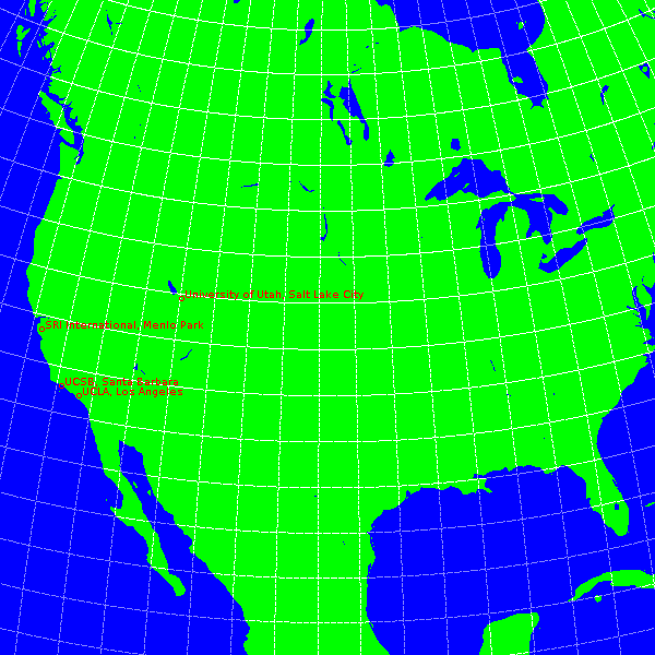
Locations of the 4 initial nodes.
At that point, the type of data was reasonably simple, mostly consisting of internal messages and small sets of data.
Stateless Design Pitfall
However, as the network grew in complexity and began to cover additional nodes aswell as their respective networks, several issues arose:
Scaling Challenges: Increasing distances and node counts rapidly highlighted NCP’s limitations.
Content-Type Evolution: New types of content began stressing NCP’s capabilities, exposing its shortcomings.
- Noise and Scalability: The protocol’s susceptibility to noise and scalability constraints became evident as the network grew beyond the original four nodes on the west coast.
- Reliability and Error Handling: NCP had no end-to-end error control mechanisms, meaning that any packet loss or errors during transmission would lead to an immediate collapse of the NCP session, rendering the connection to the host computer unusable until manual restoration would take place.
By design, NCP was a stateless communication protocol, eliminating the possibility for either party to verify the successful transmission and arrival of packets at their intended destinations. Erroneously received packets would cause Albeit, NCP did have some “stateful” features concerning the initial connection’s handshake up to the point of stating the start of an emitted datastream.

Host-to-host communication using NCP.
Furthermore, when a computer tried to connect to ARPAnet that was outside the preregistered node, would the network protocol cause that specific system’s networking functionality to fail. This was due to NCP’s inherently rigid design, which did not take in account unregistered acting nodes not residing in predefined networks.
The Advent of TCP and the Ideological Shift to Open Architecture Networking
As multitude of industries started shifting towards standardization of technologies, would it permit more free collaborative work between separate R&D entities to effectively overcome technological shortcoming in an unforeseen pace. This transformation in return reinforced the emphasis of interoperability between technologies, a concept that would become a cornerstone in the development of the Transmission Control Protocol (TCP).
Flag Day
January 1, 1983
While ARPANET’s predominant network protocol (NCP) was groundbreaking in its time, it was fundamentally constrained by its stateless architecture. Growth of the network drove more and more intricate technologies to be built on top of the existing protocol stack, a stack which did not always quarantee the stability, nor the efficiency that was needed of it.
Fortunately, those limitations were acknowledged in sure time shortly after the first major expansion of the ARPANET network. Been under active refinement since 1974, TCP emerged as a robust and efficient successor, a well-suited to supplant NCP as the primary networking protocol.
Statefully stark contrast
This new protocol would be stateful, meaning that it also maintains information about past interactions.
Statelessness to Statefulness: Introduced a robust connection model which quaranteed the packet’s succesful delivery to target. This meant that the information flow had a structured lifecycle.
Modularity and Scalability: New algorithms and hiararchical addressing for dynamic routing. The protocol was more advanced and modular than its predecessor, making it easier to develop application modules for it.
Error Correction and Flow Control: Introduction of checksums for data integrity and acknowledgements for reliable data delivery. Bandwidth optimizations and utilization based on nework conditioning were also implemented.
Reliability and Error Handling: Embedded sequence number, making it possible to request only the corrupted or missing packets from a stream. This way the whole stream wouldn’t need to be retransmitted. Additionally, packets would also incorporate more describing data, metadata, to ensure better handling across its lifecycle.
Given the new way of segmenting packets with each their own metadata, it would allow multiple streams of data to multiple peers take place. This would be called multiplexing in the domain of simultaneous information exchange between multiple nodes.
Technical details and fundamentals of TCP
Let’s abstract the architechtural framework of TCP/IP by juxtaposing it with a more recognizable OSI-model.

Let’s condense the functionality of each layer of the TCP/IP framework.
Application Layer:
Handles the Protocol Data Units (PDUs) of each established instance.
This includes management and formatting of end-user interface functionality, aswell as capsulation processes for higher level protocols, such as HTTP and FTP.Transport Layer:
Manages end-to-end communication, data segmentation, and error checking.
This is the layer which processes the bi-directional encapsulation, aswell as decapsulation of base-protocol manifesting as TCP and UDP segments.
The layer also dictates the featured parameters embedded in base-protocol’s metadata.
Error checking and flow control are also notable functions employed in here.Network Layer:
Tasked with packet forwarding and routing, this layer deals in logical addressing of hosts. Operations relating to protocol IP from the TCP/IP stack happen here.
IP stands for “Internet Protocol”, and it governs over establishing of logical data paths over the networks.
Network Address Translation (NAT) would be one of the layer’s complex operations which is performed here.Network Access Layer:
Also known as the Link Layer, it encompasses the Data Link and Physical layers of the OSI model.
Handling of hardware-level framing and addressing them to the network’s transmittable medium via physical links and connections is performed here.
The Three-way Handshake of TCP
Inspecting this sample Wireshark capture, we can see the whole process of TCP connection lifecycle happen.
The three-way handshake outlines well the cornerstone of TCP and its fundamentals when establishing a network flow featuring reliable, ordered and error-checking data stream between a client and a server.
And here we can see the flow chart of these transactions:

TCP SYN bit:
During the initiation of a TCP connection, both parties must align their individual Sequence Numbers (SEQ), a process encapsulated by the term “SYN”, which stands for “Synchronize Sequence Numbers.”
SYN, SYN-ACK, ACK
This occurs at the very start of a new stream, where the packets do not yet contain a payload, but contain relevant parameters embedded in the packet’s header.
As stated, the SYN Bit itself situated in the Flags section of a TCP header. When this flag is set to 1, specifying a random Initial Sequence Number (ISN) it is marked as the starting point for the sequence.
Upon receiving the SYN packet, the server ACKnowledges the sender’s sequence number and in return, reciprocates by sending its own sequence number aswell as acknowledgement of the previously received sequence number.
Then in the last stages, the client obtains a package containing both server participant’s sequence number in conjunction with confirmation that the server has acknowledged client’s sequence number.
Handshake is completed as the final acknowledgement confirming that the server’s sequence number was received by the client.
TCP ACK and SEQ numbering:
Inventive architecture of TCP allows for reliable data transmission over unreliable networks. In this context, a few noteworthy characteristic would be crucial to understand from its well-known idiosyncratic mechanisms.
ACK acknowledges the receipt of bytes and indicates the next byte that is to be expected. Sequentially, it signifies that all bytes up to (ACK - 1) have been successfully received. The server is then expected to base its next transmission on this corresponding ACK number.
SEQ signifies the ordinal position of the first byte in that segment within the relation to the overall byte stream of the connection. Essentially tagging the first byte makes the connection Stateful considering that respective subsequent packets are incremented for bytes of the transmitted payload.
Any loss of transmitted data results in desynchronization of mutually agreed upon metered sequence numbering. This breaks the implicity of one either parties previously aligned SEQ- counter, which then triggers a conditional routine informing the peer of the last undisrupted packet sequence number by annoting the request for retransmission starting from that ordinal position.
TCP connection states LISTENING and ESTABLISHED:
Before a live connection can be set up, must there be a server application ready to receive incoming connections for the requested service on its designated port.
As this server-side application is tethered to an addressable network location, and in fact is prepared to entertain inbound connection requests with an outbound capable service application, answering the requested SYN with a corresponding ACK. This effectively informs the requesting party of remote application’s availability over specified route, therefore symbolizing the state-describing abstraction that the connected peer is LISTENING
Moving forward, presuming both parties successfully concluded the aforementioned handshake, endpoints transition from a state of LISTENING to ESTABLISHED. This shift demarcates the instantiation of a fully functional TCP communication channel.
 |
|---|
| This diagram visually represents the TCP connection lifecycle from a client’s perspective, delineating each state transition from initiation to termination. |
TCP&UDP with Ports:
Dealing with application data (Payloads) in our schema.
Take for an example the following diagram down below, visualizing an HTTP link session between a client and a server.

Source:
Ascending in the network topological layer, we are working with encapsulated sets of application instructions and context.
Given a reasonable end-to-end connectivity, the client can initiate requests for server-application services. Additionally, multiple connections to multiple servers can be concurrently initiated and maintained. This is due to the design approach employed most distinctively by TCP/IP protocol stack which characterises each unique session by its socket pairs.
Functionally, client requested connections leverage ephemeral (temporary) ports, which the client’s system allocates randomly, typically from a predefined range above 1024. However, IANA (Internet Assigned Numbers Authority) alongside majority of OS vendors and device manufacturers recommend this range to be in 49152 – 65535 range.

Destination:
As previously discussed, server-endpoints listen for incoming client requests on specific, well-defined ports, from which “Well-known” ports ( 0 – 1023 ) were once standartized. All relevant, universally crucial protocols, and most essential application services are mapped within that range, maintaining integrity for clients by making service-discovery of application-specific routes more readily available.
Furthermore, while the well-known ports cater to predefined services, there are also other ranges above 1023. Such aforementioned ranges compose of multitude of lesser known, but still relevant service applications and protocols.
Regarding governing over these ranges, IANA oversees the registration of these ports to prevent overlapping uses.
Overview of service ports over TCP
- Ports: 22, 23, 25, 80, 443, 445, 3306
| Port | Protocol | Description |
|---|---|---|
| 22 | SSH | Secure Shell for encrypted remote login sessions |
| 23 | Telnet | Remote terminal access, unencrypted |
| 25 | SMTP | Simple Mail Transfer Protocol for email routing |
| 80 | HTTP | HyperText Transfer Protocol, web content |
| 443 | HTTPS | HTTP over SSL/TLS, encrypted web content |
| 445 | SMB | Server Message Block for Windows file sharing |
| 3306 | MySQL | MySQL database system communication |
These ports prominently stem from the previously discussed “Well-known” range of ports with the exception of 3306, MySQL.
For that service-port is recognized in the category of “registered ports” as per IANA’s definition.
| Range | Director | Description |
|---|---|---|
| 0-1023 | IANA | Well-Known Ports |
| 1024-49151 | IANA | Registered Ports |
| 49152-65535 | Private/Unassigned | Dynamic/Private Ports |
Outlining some UDP specifics

As seen from above, UDP’s operational complexity is unalike that of TCP’s.
Design methodology UDP makes it the protocol of choice for scenarios where low latency and high throughput are paramount, even if it comes at the cost of potential data loss.
UDP being ”connectionless”:
As TCP was described being a ”Connection-oriented protocol”, can distinction be derived for its ”Stateful” design from the characteristics we detailed earlier.
For the evidence of interchangeably used terms used in contrast can we describe UDP to being a ”Connectionless” protocol where ”Stateless” characteristics are revealed.
Elaborating on the significant drawbacks of UDP’s connectionless protocol;
- Does not establish a dedicated connection before sending data to the recipient.
- Unlike its stateful counterpart TCP, UDP by design does not have builtin mechanisms for session management.
UDP Lack flow-control features:
Architectural design of UDP does not leave room for additional operations involving stateful mechanisms such as sliding windows or acknowledgements.
Since it does not receive feedback of neither participant’s state, or context about the ongoing communication, implementing flow-control would be challenging.
For same aforementioned reasons, risk for network congestation is evident, especially when dealing with high datarates.
UDP services prefer max 512 byte datagrams:

The reason for this particular byte size implementation is rather multifaceted.
Historical protocol specifications from RFC791, which touches upon the concept of fragmentation and datagram sizes, also guidelines this byte size with a premise that most networks would be able to sufficiently handle at least an 512-byte UDP datagram plus necessary headers without resorting to fragmentation. Even though this datagram size is not an technological limitation concerning current architecture of these protocols, this practise is still somewhat frequently indulged upon with compatability in mind.
Additionally, general consensus upon the belief that smaller datagram help reduce fragmenting and potential for dropped packets.
Cases where using UDP is more beneficial than TCP:
There are several scenarios where UDP’s more simplistic approach yelds greater benefits compared to TCP.
| Use Case | Advantage |
|---|---|
| Real-time Communications | Timely delivery priority |
| DNS Queries | Short, one-off requests |
| Streaming Media | Continuous flow essential |
| Broadcast and Multicast | One-to-many communication |
| Simple Query/Response | Brief queries & responses |
| Online Gaming | Real-time state updates |
| Low Overhead | Fewer headers, faster |
| Stateless Interactions | Quick data exchange |
Advanced TCP and UDP features
TCP Header Format | RFC793
1
2
3
4
5
6
7
8
9
10
11
12
13
14
15
16
17
18
19
    0                   1                   2                   3
    0 1 2 3 4 5 6 7 8 9 0 1 2 3 4 5 6 7 8 9 0 1 2 3 4 5 6 7 8 9 0 1
   +-+-+-+-+-+-+-+-+-+-+-+-+-+-+-+-+-+-+-+-+-+-+-+-+-+-+-+-+-+-+-+-+
   |          Source Port          |       Destination Port        |
   +-+-+-+-+-+-+-+-+-+-+-+-+-+-+-+-+-+-+-+-+-+-+-+-+-+-+-+-+-+-+-+-+
   |                        Sequence Number                        |
   +-+-+-+-+-+-+-+-+-+-+-+-+-+-+-+-+-+-+-+-+-+-+-+-+-+-+-+-+-+-+-+-+
   |                    Acknowledgment Number                      |
   +-+-+-+-+-+-+-+-+-+-+-+-+-+-+-+-+-+-+-+-+-+-+-+-+-+-+-+-+-+-+-+-+
   |  Data |           |U|A|P|R|S|F|                               |
   | Offset| Reserved  |R|C|S|S|Y|I|            Window             |
   |       |           |G|K|H|T|N|N|                               |
   +-+-+-+-+-+-+-+-+-+-+-+-+-+-+-+-+-+-+-+-+-+-+-+-+-+-+-+-+-+-+-+-+
   |           Checksum            |         Urgent Pointer        |
   +-+-+-+-+-+-+-+-+-+-+-+-+-+-+-+-+-+-+-+-+-+-+-+-+-+-+-+-+-+-+-+-+
   |                    Options                    |    Padding    |
   +-+-+-+-+-+-+-+-+-+-+-+-+-+-+-+-+-+-+-+-+-+-+-+-+-+-+-+-+-+-+-+-+
   |                             data                              |
   +-+-+-+-+-+-+-+-+-+-+-+-+-+-+-+-+-+-+-+-+-+-+-+-+-+-+-+-+-+-+-+-+
Structure of TCP base-header as first seen in RFC793
User Datagram (UDP) Header Format | RFC768
1
2
3
4
5
6
7
8
9
10
11
12
                  0      7 8     15 16    23 24    31
                 +--------+--------+--------+--------+
                 |     Source      |   Destination   |
                 |      Port       |      Port       |
                 +--------+--------+--------+--------+
                 |                 |                 |
                 |     Length      |    Checksum     |
                 +--------+--------+--------+--------+
                 |
                 |          data octets ...
                 +---------------- ...
Structure of UDP base-header as first seen in RFC768
TCP header length without extra options:
Examining the following sample displaying no applied extra options, we can observe the header length to be 20 bytes.
This is also defined in RFC793, albeit solely by diagram interpretation as previously showcased.
Furthermore, we should take in consideration minimum header sizes of lower layers consisting of L1 (Ethernet) to L3 (TCP) frames by abstraction.
14 bytes
20 bytes
20 bytes
4 bytes
Estimating for components attributing zero additional information, only satisfying minimum header bytesizes, would total bytesize settle at 58 bytes.
For it to align with an functional bytesize according to standard of 64 bytes, does it have to include additional bytes as variables, or alternatively, use 6 bytes for padding.
Which brings us to the final overview of packet analysis by structural abstraction.
The following outlines UDP packet’s field diagram.
UDP header length :
| Source Port (16) | Destination Port (16) | ||
| Length (16) | Checksum (16) |
UDP header has a fixed length of 8 bytes and does not natively feature additional attributes.
Its header size is always 8 bytes, regardless of the payload.
Evaluating Nagle’s algorithm on TCP:
This particular algorithm refers to a technique in the realm of TCP optimizations.
Concerned with the “small-packet” problems, where protocol overhead from packet encapsulation makes up a disproportionate amount of the composed packet’s size causes inefficiency in the realm of packet-switching network environments.
In solution, Nagle’s algorithm employs flow-control which condenses multiple smaller packets into one, given that the following conditional rules are apply:
| Condition | Nagle’s Action |
|---|---|
| Unacknowledged Data | Takes action, packet composition process employed |
| Buffer Size ≥ MSS | Sends the “full” packet right away |
| TCP_NODELAY` Flag Set | Prohibit from intefering |
| Delayed ACK Interaction | May hold off (synergistic) |
– Applicable synergistic effects with delayed ACK
[Flow chart]
– In-flight [Wireshark_diagram]
– Silly window scenario…
[Wireshark_waterfall_windows]
– Delayed ACK…
– Bits about network congestation… RFC896
”Quote”
– Benefits&Tradeoffs
Use of “keepalive” mechanism to maintain established connection:
Typically, protocols base their connection management on the perceived state which their assosicated endpoint is, and wether or not they’re reachable.
During routine operation, where established connection between parties exhibit active exhange of packets, sustaining the session’s validity, and thus effectively preventing premature termination of that connection.
Conversely, in instances where neither party is actively transmitting application data, keepalive mechanisms come to act as countermeasures. Primarily, keepalive packets offer a way to maintain an established connection by providing periodic evidence of the session’s continued relevance.
Raw sockets:
Abstracting
Prerequisites
Analyzing
Summary
Conclusion
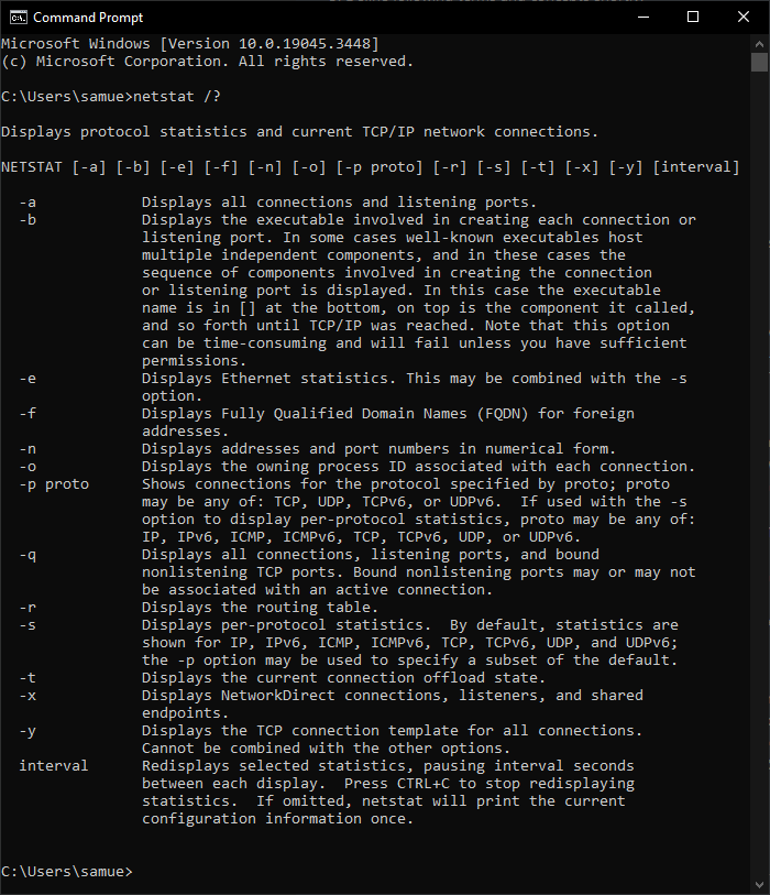
Extra Netstat command options and information